Featured Solutions Y Strainer Simplex Basket Strainer Duplex Strainer Tee Strainer Automatic Strainer Conical Strainer Suction Diffuser Wafer Strainer Accessories Company Resources Contact us
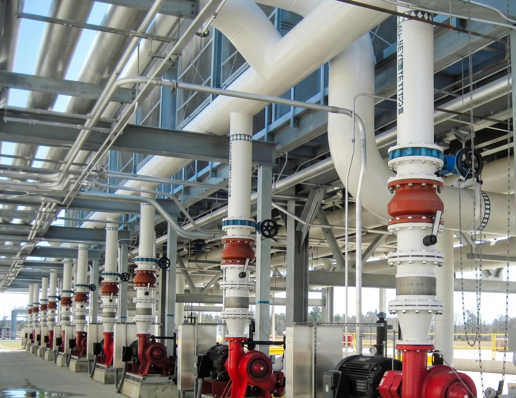
Pump and compressor suction strainer — application image to follow
Solution 02

Pump & Compressor
Suction Strainers

Suction-side protection for rotating equipment — sized to the suction condition, not the line size alone.

Typical Types
Y · Basket · Duplex
Primary Risk
Particulate wear
Key Trade-off
Filtration vs. Δp
Continuous Duty
Duplex arrangement
02 — Overview

What is a suction strainer?

A piping component installed directly upstream of rotating equipment to remove particulate contamination — welding debris, rust, scale and pipe slag — before it reaches the pump or compressor. Impellers, seals and bearings are precision-machined with tight clearances, so they are far more sensitive to particulate damage than most other equipment in a process system.

Unlike general pipeline protection, suction strainer selection has to account for the hydraulic sensitivity of the suction side. Pressure drop across the strainer directly reduces the pressure available at the equipment inlet — which is why sizing here receives closer engineering attention than elsewhere in the piping system.

03 — The Engineering Challenge

Three risks on the suction side

01 / Contamination

Particulate Damage

Debris entering suction lines can produce impeller wear, seal damage and bearing wear — the risk is highest during commissioning or after piping work upstream.

02 / Hydraulics

Pressure Margin

Any strainer adds pressure drop, reducing the pressure available at the inlet. Suction margins are often already limited, so sizing needs real headroom.

03 / Access

Maintenance Interruption

Cleaning normally takes the line out of service unless a duplex arrangement is used. Basket access has to be planned into the layout, not added later.

04 — Our Engineering Solution

Sized to the suction condition

The strainer is positioned directly upstream of the inlet, with basket or screen sizing based on the required flow rate and an allowable suction-side pressure drop established for that specific application. Filtration rating is selected to suit the expected particulate size and the equipment's sensitivity, balanced against the pressure-drop and dirt-holding implications of a finer screen.

Body orientation and connection type are arranged to suit the suction piping layout, with attention to maintaining stable, non-turbulent flow approaching the inlet. Where interruption for cleaning is not acceptable, a duplex arrangement keeps one chamber in service while the other is drained and cleaned.

05 — How We Engineer the Solution

The selection sequence

Six governing inputs, one evaluation, four engineered outputs. On suction service the allowable pressure drop and NPSH-related constraints carry more weight than anywhere else in the line.

PROCESS INPUTSEVALUATIONENGINEERED OUTPUTFlow rateSuction line sizeFluid propertiesRequired filtration ratingAllowable suction-side ΔpNPSH-related constraintsSUCTIONSTRAINERSIZINGConfiguration — Y / basket / duplexScreen & basket open areaMaterial selectionMaintenance arrangement

Pressure drop is one of several contributors to available suction pressure — it is evaluated against the equipment's suction hydraulic requirement, not in isolation.

06 — Strainer Selection

Which configuration fits?

RequirementPossible Solution
Compact installation, moderate dirt loadY Strainer · Tee Strainer · Wafer Strainer
Higher dirt-holding capacity requiredBasket Strainer
Continuous operation, no acceptable downtime for cleaningDuplex Basket Strainer · Automatic Strainer
Temporary commissioning-only protectionTemporary Cone Strainer

No single strainer type is universally correct for suction service. Final selection depends on flow rate, allowable suction-side pressure drop, line size, fluid properties, filtration requirement and the maintenance philosophy for the specific installation.

07 — Design Parameters

What we need to size it

Send these twelve and we can size a suction strainer properly. Partial data is fine — we will tell you what is missing.

Fluid / Service
Process medium
Suction Line Size
Nominal bore
Flow Rate
Design / normal
Operating & Design Pressure
Suction side
Operating & Design Temperature
Suction side
Allowable Pressure Drop
Suction margin
Required Filtration Rating
Particulate size
Material Requirement
Fluid compatibility
End Connection
Flanged / threaded
Installation Orientation
Piping layout
Drain Requirement
Chamber drain-down
Maintenance Philosophy
Single vs. duplex
08 — Typical Applications

Where this is used

Pump suction linesCompressor suction linesBoiler feedwater pump protectionCooling-water pump systemsProcess transfer pump protectionRotating equipment commissioning

What this achieves

Helps protect rotating equipment from debris-related wear and damage
Supports stable suction-side flow conditions
Facilitates scheduled basket inspection and cleaning
Helps manage suction-side pressure-drop requirements
Supports continuous operation where a duplex arrangement is specified
10 — Materials & Installation

Selected for the application

Suction strainer bodies, baskets and internals are selected for compatibility with the process fluid and service conditions, in cast or fabricated construction depending on the application, line size and project requirements. Specific material grades and construction methods should be confirmed against the actual fluid, pressure and temperature conditions for each project — material selection is application-specific rather than fixed.

Planning for access

Install with adequate straight-pipe run and clearance so the basket or screen can be removed without disturbing suction piping alignment. Establish cleaning frequency from observed pressure-drop increase rather than a fixed interval. Where the line cannot tolerate an out-of-service period, consider a duplex arrangement at design stage rather than adding it later.

11 — FAQ

Common selection questions

Directly upstream of the pump or compressor inlet, with enough straight pipe run and access clearance to remove the basket or screen for cleaning without disturbing suction piping alignment.

No. A strainer does not prevent cavitation. What it does is add pressure drop on the suction side, which reduces the pressure available at the pump inlet. Because of that, strainer pressure drop must be accounted for in the suction-side hydraulic evaluation alongside static head, line losses and fluid vapour pressure.

Cleaning frequency depends on debris loading. It is better established from the observed pressure-drop increase across the strainer than from a fixed calendar interval alone.

Where the line cannot tolerate an out-of-service period for cleaning. A duplex arrangement lets one chamber stay in service while the other is drained and cleaned — but it should be specified at design stage rather than retrofitted.

Not automatically. A finer filtration rating increases pressure drop and reduces the time between cleanings for the same dirt load. The rating should be matched to the equipment's sensitivity and the expected particulate size, not simply minimised.

Flow rate, suction line size, fluid and service, operating and design pressure and temperature, allowable pressure drop, required filtration rating, material requirement, end connection, orientation and your maintenance philosophy.

13 — Technical Enquiry

Request engineering assistance